<?xml version="1.0" encoding="utf-8"?><feed xmlns="http://www.w3.org/2005/Atom" ><generator uri="https://jekyllrb.com/" version="3.10.0">Jekyll</generator><link href="https://chrdavis.github.io/feed.xml" rel="self" type="application/atom+xml" /><link href="https://chrdavis.github.io/" rel="alternate" type="text/html" /><updated>2025-05-28T21:37:28+00:00</updated><id>https://chrdavis.github.io/feed.xml</id><title type="html">Chris Davis’ Blog</title><subtitle>A blog about stuff.</subtitle><author><name>Chris Davis</name></author><entry><title type="html">Windows Performance Analyzer Dark Mode</title><link href="https://chrdavis.github.io/Windows-Performance-Analyzer-Dark-Mode/" rel="alternate" type="text/html" title="Windows Performance Analyzer Dark Mode" /><published>2022-03-31T00:00:00+00:00</published><updated>2022-03-31T00:00:00+00:00</updated><id>https://chrdavis.github.io/Windows-Performance-Analyzer-Dark-Mode</id><content type="html" xml:base="https://chrdavis.github.io/Windows-Performance-Analyzer-Dark-Mode/"><![CDATA[<p>As a performance dev who mostly works on Windows, I spend a substantial amount of my time staring at <a href="https://docs.microsoft.com/en-us/windows-hardware/test/wpt/windows-performance-analyzer">Windows Performance Analyzer (WPA)</a>.  It is a great tool for discovering performance issues once you get the hang of it. WPA has been around in some form for over a decade.  During that time it’s user interface hasn’t changed much.  It looks very much dated in the Vista/Win7 timeframe.</p>

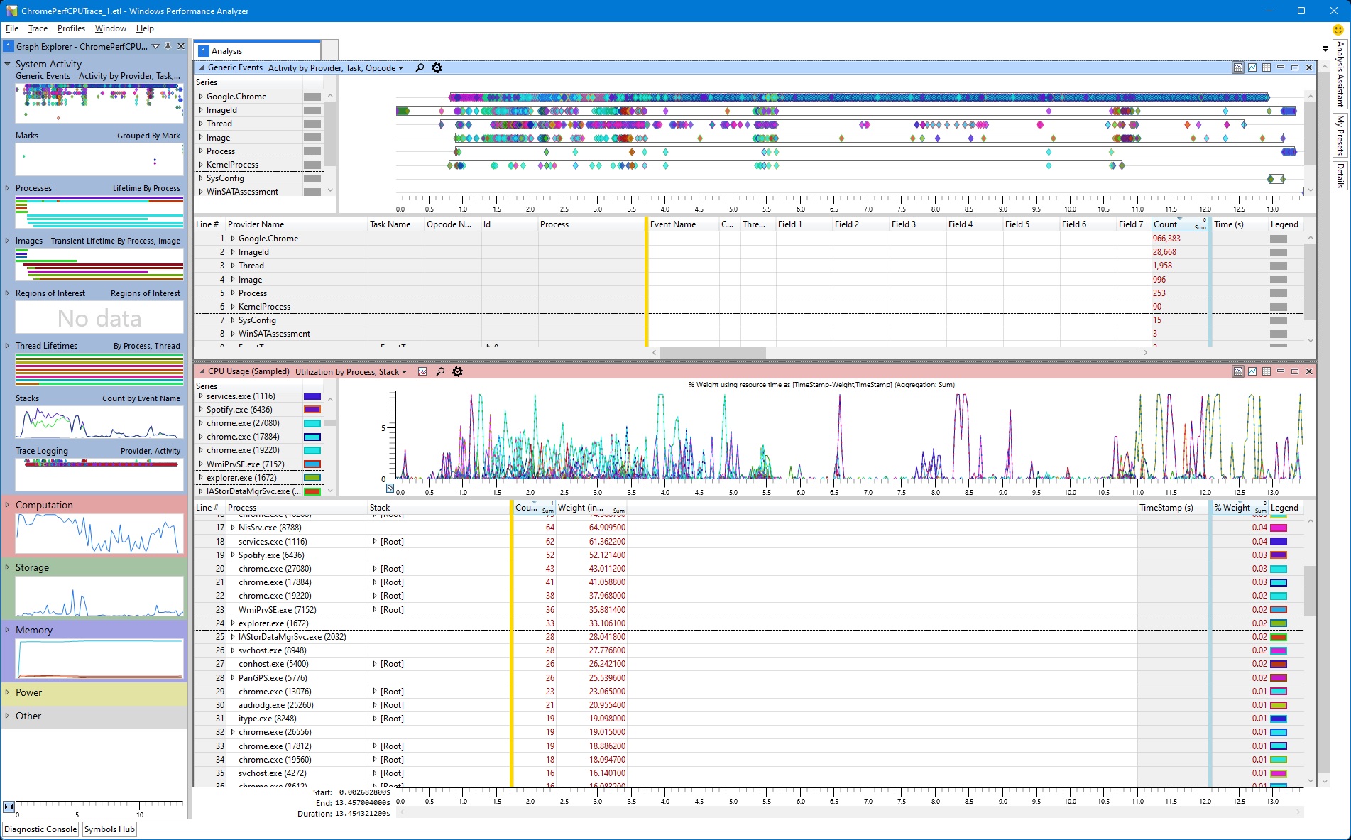
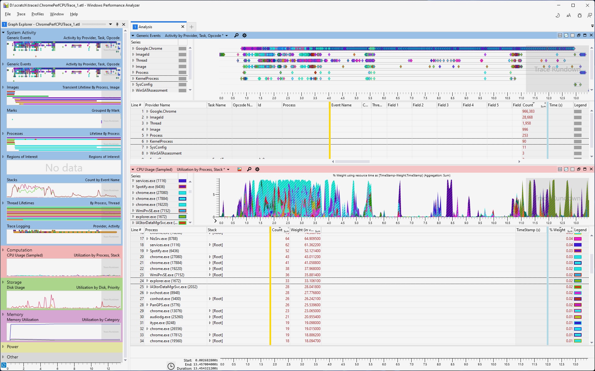
<p><img src="/assets/images/WPA_Old.jpg" alt="WPA Current UI" /></p>

<p>In January of 2021 I came down with shingles in my left eye.  I attempted to do some performance investigations in WPA but the light UI was too bright for my sensitive eye.  It was incredibly unconfortable.  I tried switching to High Contrast Black, but that is just a terrible experience all together.</p>

<p><img src="/assets/images/WPA_HighContrastBlack.jpg" alt="WPA Current High Contrast Black" /></p>

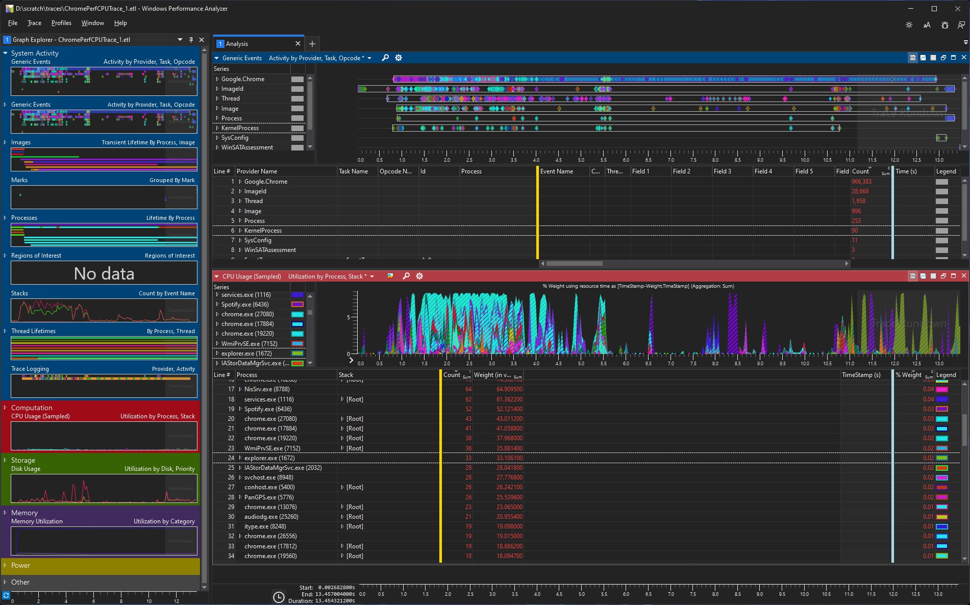
<p>What I would have given at the time for a Dark Mode in WPA.  After recovering I set out to add this.  Turns out the WPA owners were extremely welcoming of an outside developer at Microsoft working in their codebase.  What began as a short side-project turned into something more substantial than I initially anticipated.  Along the way I fixed some other UI issues that had bothered me over the years.  After a few months I was at a point where I put up a PR.</p>

<p><img src="/assets/images/WPA_LightMode.jpg" alt="WPA Light Mode" /></p>

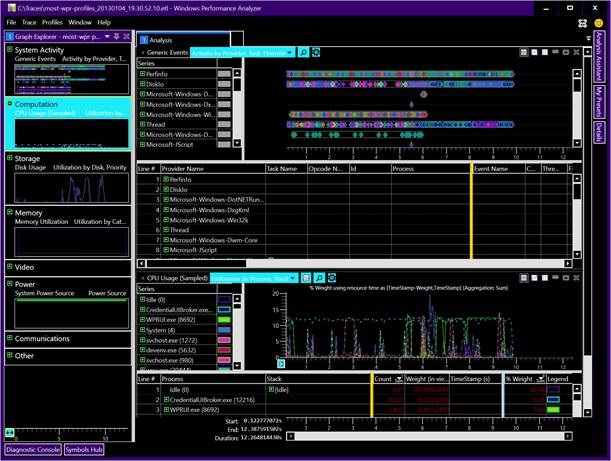
<p><img src="/assets/images/WPA_DarkMode.jpg" alt="WPA Dark Mode" /></p>

<div class="language-plaintext highlighter-rouge"><div class="highlight"><pre class="highlight"><code>Changes
• Removed old Vista-era styling
• Replaced low-res PNG resources with font glyphs for better scaling on high DPI screens.
• Bad borders, margins, button sizes fixed
• Consistent themes
• Fixed high contrast issues
• Custom title bar area
• Light and Dark modes with appropriate text, foreground and background colors
• Consistent with other modern UI
</code></pre></div></div>]]></content><author><name>Chris Davis</name></author><summary type="html"><![CDATA[As a performance dev who mostly works on Windows, I spend a substantial amount of my time staring at Windows Performance Analyzer (WPA). It is a great tool for discovering performance issues once you get the hang of it. WPA has been around in some form for over a decade. During that time it’s user interface hasn’t changed much. It looks very much dated in the Vista/Win7 timeframe.]]></summary></entry><entry><title type="html">I Killed The Windows Desktop Cleanup Wizard</title><link href="https://chrdavis.github.io/I-Killed-The-Windows-Desktop-Cleanup-Wizard/" rel="alternate" type="text/html" title="I Killed The Windows Desktop Cleanup Wizard" /><published>2019-12-01T00:00:00+00:00</published><updated>2019-12-01T00:00:00+00:00</updated><id>https://chrdavis.github.io/I-Killed-The-Windows-Desktop-Cleanup-Wizard</id><content type="html" xml:base="https://chrdavis.github.io/I-Killed-The-Windows-Desktop-Cleanup-Wizard/"><![CDATA[<p>Over almost two decades at Microsoft I have worked on a lot of stuff.  While shipping great products and features makes you feel great, I’ve found removing the terrible stuff is far more satisfying.  Nothing brought me more joy than killing the Windows Desktop Cleanup Wizard.</p>

<p align="center">
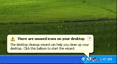
  <img src="/assets/images/DesktopCleanupWizBalloon.png" alt="Desktop Cleanup Wizard Balloon Tip" />
</p>

<p>Many will recall, <a href="https://medium.com/@dfeldman/writing-notifications-that-dont-suck-60a90256efe5">and not fondly</a>, that annoying balloon tip that would pop up from the system tray in Windows XP.  While it was distracting it was also confusing for those with no icons on their desktop aside from the Recycle Bin.  Microsoft’s own design docs call it out amongst the <a href="https://docs.microsoft.com/en-us/windows/win32/uxguide/mess-notif#design-concepts">Windows XP Hall of Shame</a> for “annoying, inappropriate, useless, irrelevant notifications”.</p>

<p>The Desktop Cleanup Wizard first appeared in late 2000 during Windows XP development and was referred to internally as the folder cleaner (fldrclnr.dll).  I removed the code late in the Windows Vista product cycle.    Digging around recently I found the code change:</p>

<blockquote>
  <p>Change 280177 by WINGROUP\chrdavis@SHBLD25 on 2006/04/30 23:24:22
BUG: 1575578: Remove fldrclnr from build</p>
</blockquote>

<p>Unlike big game hunters who can hang their trophies over their mantel to humble brag to their acquaintances, this blog post will have to do.</p>

<p align="center">
  <b>R.I.P.</b><br />
  <b>Desktop Cleanup Wizard</b><br />
  <b>2000 - 2006</b><br />
</p>

<p>It has been 13 years since the code has been removed and 5 years since support for Windows XP ended. Yet, I still see the little bastard on old point of sale or tv displays every now and then at the mall or the airport.  The reality is it will outlive us all.</p>

<h3 id="update">UPDATE</h3>
<p>After going through the code changes some more I found that my friend Aidan Low had removed the infamous balloon tip almost a year prior to my change that removed the feature entirely.  Ah well.</p>

<blockquote>
  <p>Change 166922 by NTDEV\aidanl@SHBLD04 on 2005/07/12 13:30:35
Remove “you have unused icons” balloon. The end of an era; one of the major annoyances of XP is now gone.</p>
</blockquote>]]></content><author><name>Chris Davis</name></author><summary type="html"><![CDATA[Over almost two decades at Microsoft I have worked on a lot of stuff. While shipping great products and features makes you feel great, I’ve found removing the terrible stuff is far more satisfying. Nothing brought me more joy than killing the Windows Desktop Cleanup Wizard.]]></summary></entry><entry><title type="html">Power Rename Ships With Microsoft Power Toys</title><link href="https://chrdavis.github.io/Power-Rename-Ships-With-Microsoft-Power-Toys/" rel="alternate" type="text/html" title="Power Rename Ships With Microsoft Power Toys" /><published>2019-10-29T00:00:00+00:00</published><updated>2019-10-29T00:00:00+00:00</updated><id>https://chrdavis.github.io/Power-Rename-Ships-With-Microsoft-Power-Toys</id><content type="html" xml:base="https://chrdavis.github.io/Power-Rename-Ships-With-Microsoft-Power-Toys/"><![CDATA[<p>Shortly after I released <a href="https://github.com/chrdavis/SmartRename">SmartRename</a> I discovered that some people at Microsoft were bringing back PowerToys.  I moved a copy of the code over to their repo and renamed SmartRename to PowerRename.  Finally, after getting dropped with the Windows Vista PowerToys 12 years ago, PowerRename finally ships!</p>

<p><img src="/assets/images/powertoyslogo.jpg" alt="PowerToys Logo" /></p>

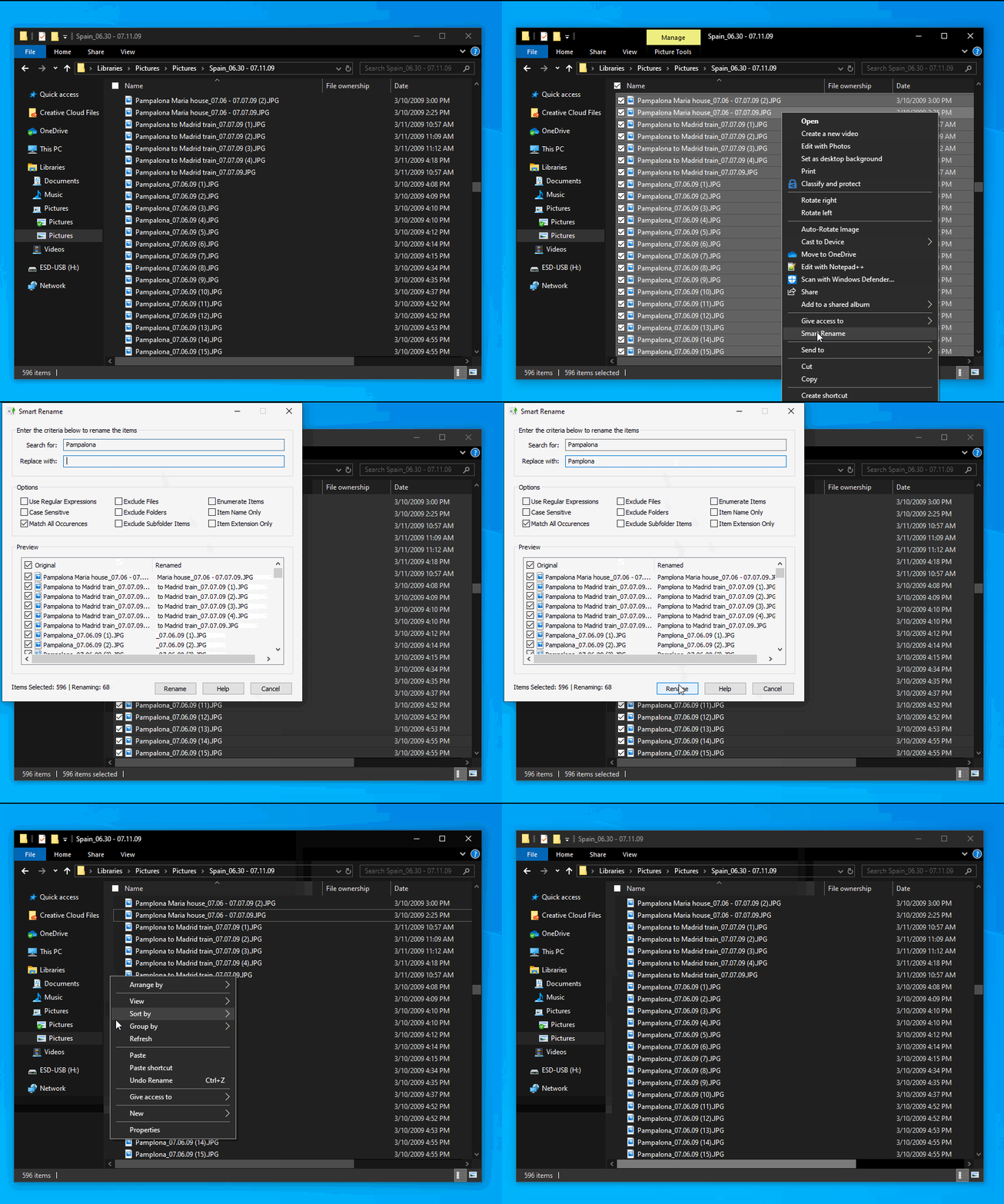
<p>Get <a href="https://github.com/microsoft/PowerToys/tree/master/src/modules/powerrename">PowerRename</a> and the rest of the <a href="https://github.com/microsoft/PowerToys">Microsoft PowerToys</a></p>]]></content><author><name>Chris Davis</name></author><summary type="html"><![CDATA[Shortly after I released SmartRename I discovered that some people at Microsoft were bringing back PowerToys. I moved a copy of the code over to their repo and renamed SmartRename to PowerRename. Finally, after getting dropped with the Windows Vista PowerToys 12 years ago, PowerRename finally ships!]]></summary></entry><entry><title type="html">Smart Rename</title><link href="https://chrdavis.github.io/Smart-Rename/" rel="alternate" type="text/html" title="Smart Rename" /><published>2019-09-16T00:00:00+00:00</published><updated>2019-09-16T00:00:00+00:00</updated><id>https://chrdavis.github.io/Smart-Rename</id><content type="html" xml:base="https://chrdavis.github.io/Smart-Rename/"><![CDATA[<p>I just released a new Windows Shell Extension - SmartRename.  It allows for simple search and replace or regular expression bulk renaming of files and folders.  I actually first wrote this extension back in 2007 after Windows Vista shipped.  It was supposed to be included in the Windows Vista PowerToys to showcase the capabilities of the new <a href="https://docs.microsoft.com/en-us/windows/win32/api/shobjidl_core/nn-shobjidl_core-ifileoperation">file operations engine</a> in Vista - which I worked on at the time.  Unfortunately, the Vista PowerToys got cancelled just as I finished it :/.  I had always wanted to get around to rewriting the extension from scratch and releasing it.  Finally after 12 years I found some time.</p>

<p>Code and installer available at the <a href="https://github.com/chrdavis/SmartRename">SmartRename Repo Page</a>:</p>

<p><img src="/assets/images/SmartRenameDemo.gif" alt="Smart Rename Demo" /></p>]]></content><author><name>Chris Davis</name></author><summary type="html"><![CDATA[I just released a new Windows Shell Extension - SmartRename. It allows for simple search and replace or regular expression bulk renaming of files and folders. I actually first wrote this extension back in 2007 after Windows Vista shipped. It was supposed to be included in the Windows Vista PowerToys to showcase the capabilities of the new file operations engine in Vista - which I worked on at the time. Unfortunately, the Vista PowerToys got cancelled just as I finished it :/. I had always wanted to get around to rewriting the extension from scratch and releasing it. Finally after 12 years I found some time.]]></summary></entry><entry><title type="html">Hacking A Mitsubishi Heat Pump Part 2</title><link href="https://chrdavis.github.io/hacking-a-mitsubishi-heat-pump-Part-2/" rel="alternate" type="text/html" title="Hacking A Mitsubishi Heat Pump Part 2" /><published>2019-07-06T00:00:00+00:00</published><updated>2019-07-06T00:00:00+00:00</updated><id>https://chrdavis.github.io/hacking-a-mitsubishi-heat-pump-Part-2</id><content type="html" xml:base="https://chrdavis.github.io/hacking-a-mitsubishi-heat-pump-Part-2/"><![CDATA[<p>In <a href="https://chrdavis.github.io/hacking-a-mitsubishi-heat-pump-Part-1/">my previous post</a> I showed how to use a cheap Arduino to connect wirelessly to a Mitsubishi heat pump to control its settings.  Yet, it still took some work to connect to the device access point/web server.  Having multiple heat pumps in your home is even more laborious.  Without a lot more work, you also couldn’t communicate directly with them from outside of your Wi-fi network.  What we need is a centralized app that can communicate with the Arduino more directly.</p>

<h3 id="mqtt">MQTT</h3>

<p>From the <a href="https://mqtt.org">mqtt.org</a> site:
<em>MQTT is a machine-to-machine (M2M)/”Internet of Things” connectivity protocol. It was designed as an extremely lightweight publish/subscribe messaging transport.</em></p>

<p>I won’t go into too much detail on <a href="http://mosquitto.org/man/mqtt-7.html">how MQTT works</a>, but it is essentially a Publish/Subscribe messaging model (publish messages/subscribe to topics).  Clients connect to a MQTT broker to subscribe to topics they want and publish messages to topics.</p>

<h3 id="hassio-and-home-assistant">Hass.io and Home Assistant</h3>

<p>From the <a href="https://www.home-assistant.io/hassio/">Home Assistant</a> site:
<em>Hass.io turns your Raspberry Pi (or another device) into the ultimate home automation hub powered by Home Assistant. With Hass.io you can focus on integrating your devices and writing automations.</em></p>

<p>Home Assistant is the centralized app we needed.  This provides the MQTT Broker (Mosquitto Add-on) and a great UI.  It also has some advanced home automation capabilities.  You can access it from your browser or from your phone via the free Home Assistant app.  To access outside your Wi-fi network you will have to enable port forwarding of the port and ip address that hass.io is running on.  See instructions for your specific router if supported.</p>

<p>The best installation instructions I have found are in the below video:
https://www.youtube.com/watch?v=qnCRcGTznXs</p>

<p>As well as the <a href="https://www.home-assistant.io/hassio/installation/">hass.io documentation</a></p>

<p>While you could <a href="https://www.home-assistant.io/docs/installation/windows/">install Home Assistant on Windows</a>, it is not fully supported and not all third-party modules work.  Because of this reason (and since I have never had the chance to play with one before) I opted to pick up a Raspberry Pi since it was the most common install platform.</p>

<p>I purchased the below Pi with a case.</p>

<p>CanaKit Raspberry Pi 3 B+ (B Plus) with Premium Clear Case and 2.5A Power Supply 
https://www.amazon.com/dp/B07BC7BMHY/ref=cm_sw_em_r_mt_dp_U_UTyiDbRW5SK29</p>

<p>I also bought a 32GB memory card for the Pi (not included in the above CanaKit)</p>

<p>Samsung 32GB EVO Plus Class 10 Micro SDHC with Adapter 80mb/s (MB-MC32DA/AM) 
https://www.amazon.com/dp/B00WR4IJBE/ref=cm_sw_em_r_mt_dp_U_VTyiDbZT8GYBT</p>

<p>After installing, be sure to install and setup the MQTT Broker (Mosquitto Add-on) so the code running on our Arduino can connect and publish MQTT messages.  Note that I had to use the ip address 172.17.0.1 (the docker network default gateway) for the broker to get it to work properly.  I found that fix in <a href="https://www.reddit.com/r/homeassistant/comments/74qqtc/hassio_mqtt_installation_beginner_questions/">this reddit post</a> to the homeassistant subreddit.</p>

<p>In Home Assistant, go to the File Editor and add the below to configuration.yaml</p>

<div class="language-ruby highlighter-rouge"><div class="highlight"><pre class="highlight"><code><span class="ss">mqtt:
  broker: </span><span class="mf">172.17</span><span class="o">.</span><span class="mf">0.1</span>
  <span class="ss">port: </span><span class="mi">1883</span>
  <span class="ss">username: </span><span class="o">&lt;</span><span class="n">my</span> <span class="n">mqtt</span> <span class="n">user</span> <span class="nb">name</span><span class="o">&gt;</span>
  <span class="ss">password: </span><span class="o">&lt;</span><span class="n">my</span> <span class="n">mqtt</span> <span class="n">password</span><span class="o">&gt;</span>
  <span class="ss">discovery: </span><span class="kp">true</span>
</code></pre></div></div>

<h3 id="code">Code</h3>

<p>UPDATED: 2/27/2020
I recently switched to using gysmo38’s MQTT module since my original post. It is much easier to deploy than the mqtt sample that was included SwiCago/HeatPump repo that relied on the HA custom component which would frequently be broken by Home Assistant updates. gysmo38’s code allows Home Assistant autodiscovery - no custom component hacking to ensure your heatpump appears in Home Assistant!</p>

<p>Download the code available at the below repo at:
https://github.com/gysmo38/mitsubishi2MQTT</p>

<p>Note - the above code will have some dependency libraries required that you will have to download through the Arduino IDE.  These include ArduinoJson and PubSubClient.</p>

<p>The features that drew me to gysmo38’s code:</p>
<ul>
  <li>Easy to deploy - you don’t need to modify the code at all.  Just flash it to your device and connect to the access point to configure it for you home wifi and mqtt server.</li>
  <li>Home Assistant autodiscovery and control with MQTT</li>
  <li>You can still control the heatpump by connecting over HTTP with a browser</li>
</ul>

<h3 id="flashing-the-arduino">Flashing the Arduino</h3>

<ol>
  <li>You don’t need to modify any code.  Just open it in Arduino IDE and upload the code to your Arduino.</li>
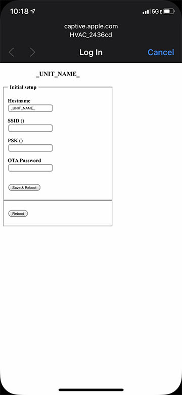
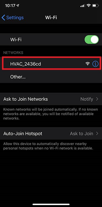
  <li>Verify you can see a new wifi access point with a name “HVAC_XXXX”.  From your phone or other wifi device, connect to the AP.</li>
</ol>

<p><img src="/assets/images/AP_Setup1.jpg" alt="Access Point of Arduino - Connecting" /></p>

<ol>
  <li>After connecting to the AP, the below will appear.  Enter a descriptive name for the device as well as the name and password for your local wifi network then click “Save &amp; Reboot”.</li>
</ol>

<p><img src="/assets/images/AP_Setup2.jpg" alt="Access Point of Arduino - Configure" /></p>

<p>After restarting, the device should be on your local wifi network.  If for some reason this step failed (ex: incorrect SSID/PW) the device will revert back to an access point. It may now require a password to connect to.  The password is the same as the name of the AP (ex: HVAC_XXXX).</p>

<ol>
  <li>Next you should configure the device to communicate with your MQTT server.  Connect to the local ip address of the arduino (ex: 192.168.1.20) with a browser.  You can log in to your wifi router to see the device and determine the ip address.</li>
</ol>

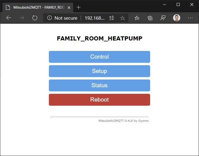
<p><img src="/assets/images/SetupHP1.jpg" alt="Setup - Main Page" /></p>

<p>Click Setup</p>

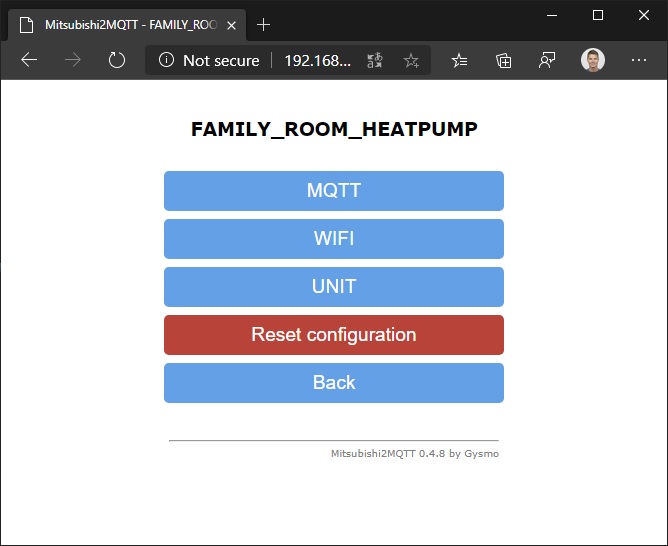
<p><img src="/assets/images/SetupHP2.jpg" alt="Setup - Setup Page" /></p>

<p>Click MQTT</p>

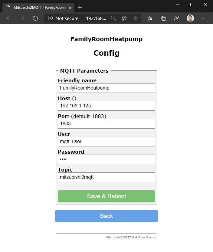
<p><img src="/assets/images/SetupHP3.jpg" alt="Setup - MQTT" /></p>

<p>Enter the required information.  Note that the host address is the ip address that Home Assistant is running on.  Also note - for the friendly name DO NOT INCLUDE SPACES! Home Assistant has issues finding devices over MQTT that have spaces in them.</p>

<p>Click “Save &amp; Reboot”</p>

<p>If you have Home Assistant installed or <a href="http://mqttfx.org/">MQTT Fx</a> you can verify that the devices are publishing MQTT messages with the default values.</p>

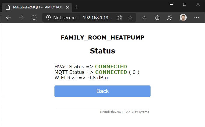
<p>After the reboot is complete, click the Status button on the front page.  This will tell you if the connection to the MQTT server was successful.</p>

<p><img src="/assets/images/SetupHP4.jpg" alt="Setup - MQTT Status" /></p>

<ol>
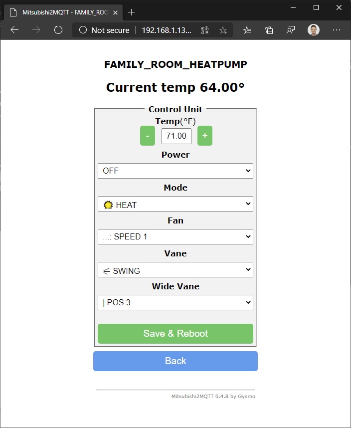
  <li>Finally, you should verify you can control your heatpump!  From the main page click the “Control” button and modify the values.</li>
</ol>

<p><img src="/assets/images/SetupHP5.jpg" alt="Control Heatpump" /></p>

<h3 id="adding-a-heat-pump-in-home-assistant">Adding a Heat Pump in Home Assistant</h3>

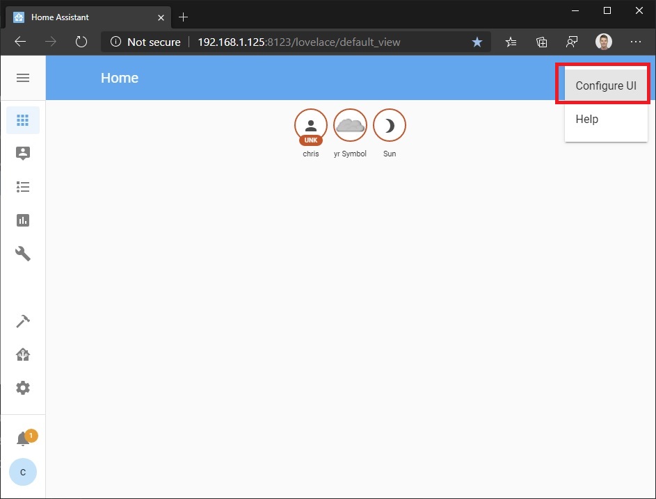
<p>From the top right menu, select Configure UI.</p>

<p><img src="/assets/images/HA_ConfigureUI.jpg" alt="Adding a Heat Pump in Home Assistant - Step 1" /></p>

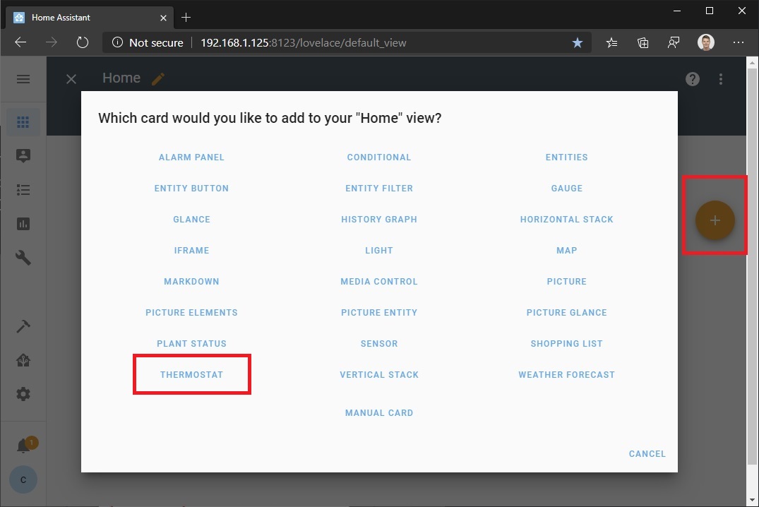
<p>Next, click the “+” button.  This will open the Card Configuration window. Click the Thermostat entry.</p>

<p><img src="/assets/images/HA_AddCard1.jpg" alt="Adding a Heat Pump in Home Assistant - Step 2" /></p>

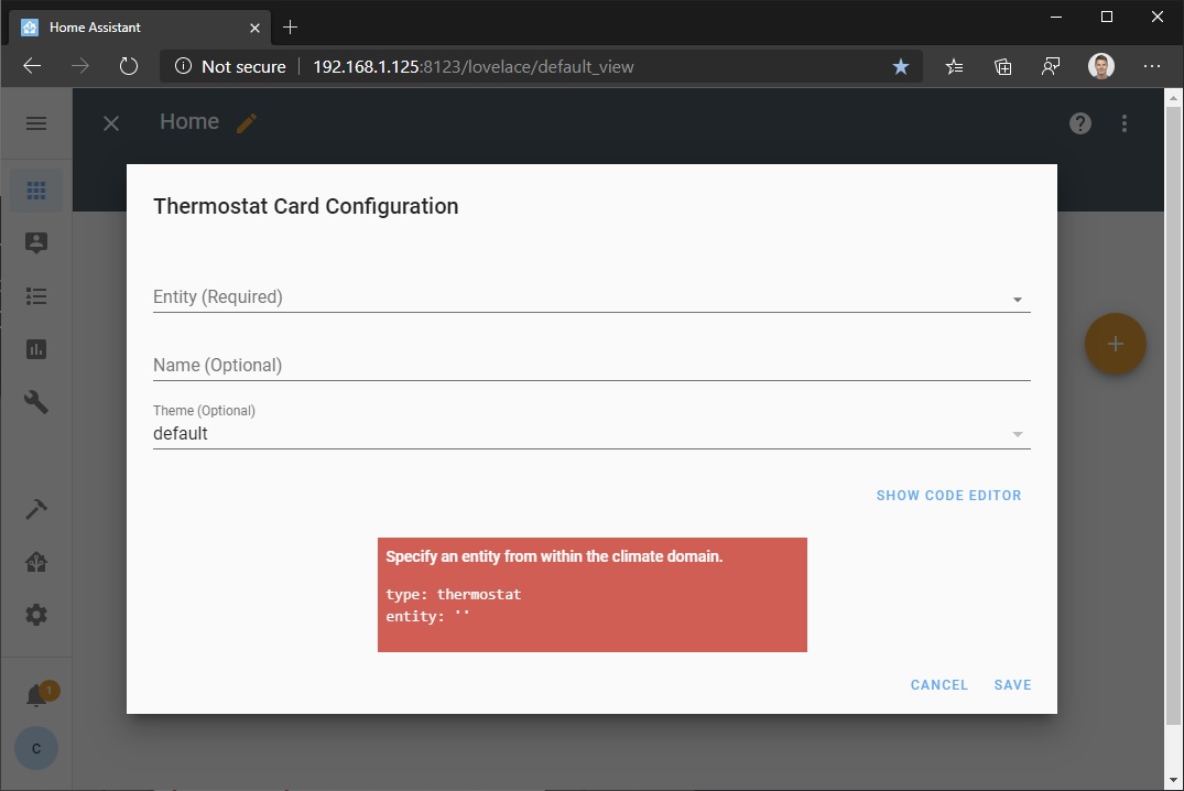
<p>The Thermostat Card Configuration window will appear</p>

<p><img src="/assets/images/HA_AddCard2.jpg" alt="Adding a Heat Pump in Home Assistant - Step 3" /></p>

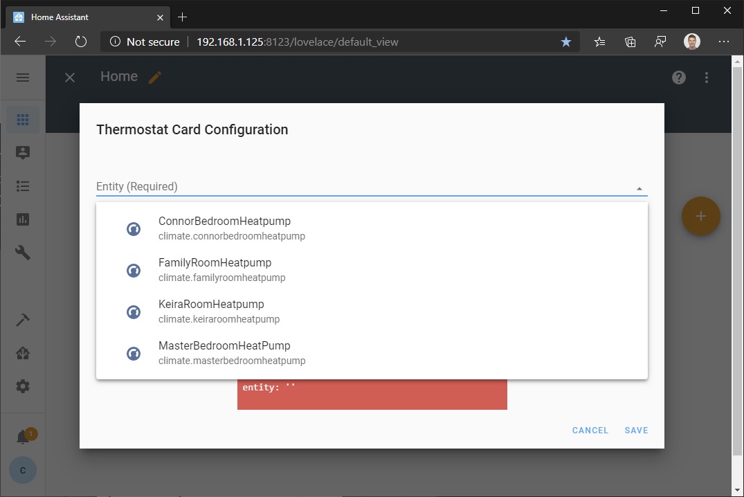
<p>From the Enitity field, click the dropdown arrow.  You should see an entry for the device you connected to your MQTT server.</p>

<p><img src="/assets/images/HA_AddCard3.jpg" alt="Adding a Heat Pump in Home Assistant - Step 4" /></p>

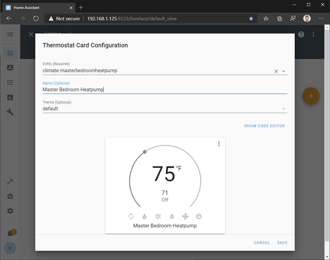
<p>You may want to give it a more readable name.</p>

<p><img src="/assets/images/HA_AddCard4.jpg" alt="Adding a Heat Pump in Home Assistant - Step 5" /></p>

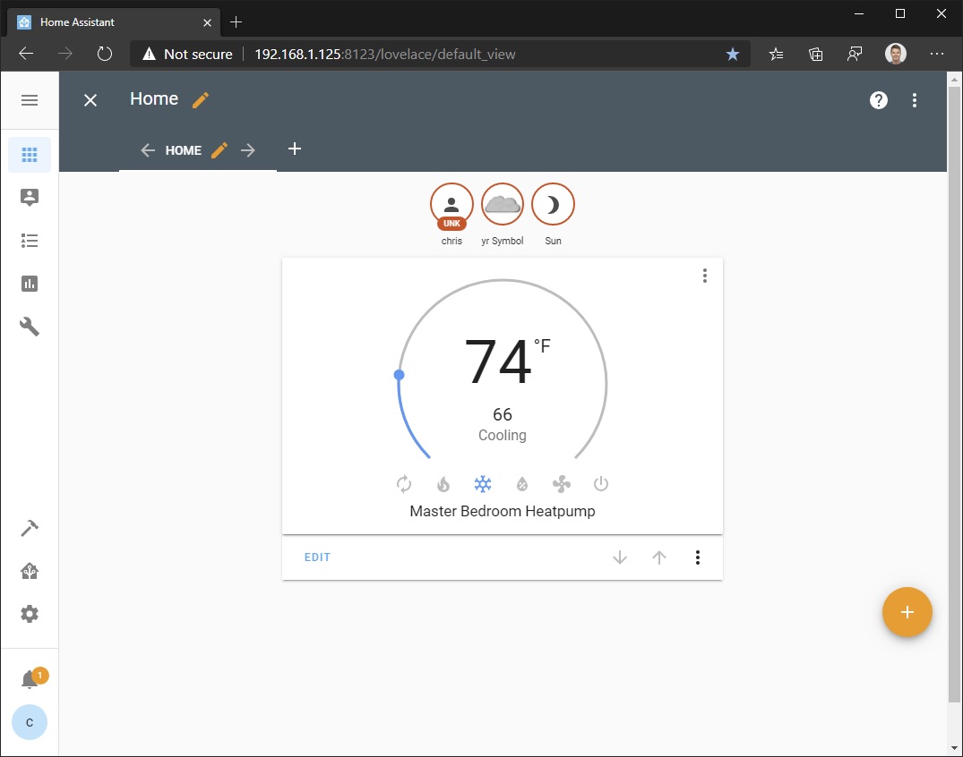
<p>The device should now be on your home screen.  Play with the settings to verify that the end-to-end communication with the heat pump is working.</p>

<p><img src="/assets/images/HA_AddCard6.jpg" alt="Adding a Heat Pump in Home Assistant - Step 6" /></p>]]></content><author><name>Chris Davis</name></author><summary type="html"><![CDATA[In my previous post I showed how to use a cheap Arduino to connect wirelessly to a Mitsubishi heat pump to control its settings. Yet, it still took some work to connect to the device access point/web server. Having multiple heat pumps in your home is even more laborious. Without a lot more work, you also couldn’t communicate directly with them from outside of your Wi-fi network. What we need is a centralized app that can communicate with the Arduino more directly. MQTT From the mqtt.org site: MQTT is a machine-to-machine (M2M)/”Internet of Things” connectivity protocol. It was designed as an extremely lightweight publish/subscribe messaging transport. I won’t go into too much detail on how MQTT works, but it is essentially a Publish/Subscribe messaging model (publish messages/subscribe to topics). Clients connect to a MQTT broker to subscribe to topics they want and publish messages to topics. Hass.io and Home Assistant From the Home Assistant site: Hass.io turns your Raspberry Pi (or another device) into the ultimate home automation hub powered by Home Assistant. With Hass.io you can focus on integrating your devices and writing automations. Home Assistant is the centralized app we needed. This provides the MQTT Broker (Mosquitto Add-on) and a great UI. It also has some advanced home automation capabilities. You can access it from your browser or from your phone via the free Home Assistant app. To access outside your Wi-fi network you will have to enable port forwarding of the port and ip address that hass.io is running on. See instructions for your specific router if supported. The best installation instructions I have found are in the below video: https://www.youtube.com/watch?v=qnCRcGTznXs As well as the hass.io documentation While you could install Home Assistant on Windows, it is not fully supported and not all third-party modules work. Because of this reason (and since I have never had the chance to play with one before) I opted to pick up a Raspberry Pi since it was the most common install platform. I purchased the below Pi with a case. CanaKit Raspberry Pi 3 B+ (B Plus) with Premium Clear Case and 2.5A Power Supply https://www.amazon.com/dp/B07BC7BMHY/ref=cm_sw_em_r_mt_dp_U_UTyiDbRW5SK29 I also bought a 32GB memory card for the Pi (not included in the above CanaKit) Samsung 32GB EVO Plus Class 10 Micro SDHC with Adapter 80mb/s (MB-MC32DA/AM) https://www.amazon.com/dp/B00WR4IJBE/ref=cm_sw_em_r_mt_dp_U_VTyiDbZT8GYBT After installing, be sure to install and setup the MQTT Broker (Mosquitto Add-on) so the code running on our Arduino can connect and publish MQTT messages. Note that I had to use the ip address 172.17.0.1 (the docker network default gateway) for the broker to get it to work properly. I found that fix in this reddit post to the homeassistant subreddit. In Home Assistant, go to the File Editor and add the below to configuration.yaml mqtt: broker: 172.17.0.1 port: 1883 username: &lt;my mqtt user name&gt; password: &lt;my mqtt password&gt; discovery: true Code UPDATED: 2/27/2020 I recently switched to using gysmo38’s MQTT module since my original post. It is much easier to deploy than the mqtt sample that was included SwiCago/HeatPump repo that relied on the HA custom component which would frequently be broken by Home Assistant updates. gysmo38’s code allows Home Assistant autodiscovery - no custom component hacking to ensure your heatpump appears in Home Assistant! Download the code available at the below repo at: https://github.com/gysmo38/mitsubishi2MQTT Note - the above code will have some dependency libraries required that you will have to download through the Arduino IDE. These include ArduinoJson and PubSubClient. The features that drew me to gysmo38’s code: Easy to deploy - you don’t need to modify the code at all. Just flash it to your device and connect to the access point to configure it for you home wifi and mqtt server. Home Assistant autodiscovery and control with MQTT You can still control the heatpump by connecting over HTTP with a browser Flashing the Arduino You don’t need to modify any code. Just open it in Arduino IDE and upload the code to your Arduino. Verify you can see a new wifi access point with a name “HVAC_XXXX”. From your phone or other wifi device, connect to the AP. After connecting to the AP, the below will appear. Enter a descriptive name for the device as well as the name and password for your local wifi network then click “Save &amp; Reboot”. After restarting, the device should be on your local wifi network. If for some reason this step failed (ex: incorrect SSID/PW) the device will revert back to an access point. It may now require a password to connect to. The password is the same as the name of the AP (ex: HVAC_XXXX). Next you should configure the device to communicate with your MQTT server. Connect to the local ip address of the arduino (ex: 192.168.1.20) with a browser. You can log in to your wifi router to see the device and determine the ip address. Click Setup Click MQTT Enter the required information. Note that the host address is the ip address that Home Assistant is running on. Also note - for the friendly name DO NOT INCLUDE SPACES! Home Assistant has issues finding devices over MQTT that have spaces in them. Click “Save &amp; Reboot” If you have Home Assistant installed or MQTT Fx you can verify that the devices are publishing MQTT messages with the default values. After the reboot is complete, click the Status button on the front page. This will tell you if the connection to the MQTT server was successful. Finally, you should verify you can control your heatpump! From the main page click the “Control” button and modify the values. Adding a Heat Pump in Home Assistant From the top right menu, select Configure UI. Next, click the “+” button. This will open the Card Configuration window. Click the Thermostat entry. The Thermostat Card Configuration window will appear From the Enitity field, click the dropdown arrow. You should see an entry for the device you connected to your MQTT server. You may want to give it a more readable name. The device should now be on your home screen. Play with the settings to verify that the end-to-end communication with the heat pump is working.]]></summary></entry><entry><title type="html">Hacking A Mitsubishi Heat Pump Part 1</title><link href="https://chrdavis.github.io/hacking-a-mitsubishi-heat-pump-Part-1/" rel="alternate" type="text/html" title="Hacking A Mitsubishi Heat Pump Part 1" /><published>2019-07-01T00:00:00+00:00</published><updated>2019-07-01T00:00:00+00:00</updated><id>https://chrdavis.github.io/hacking-a-mitsubishi-heat-pump-Part-1</id><content type="html" xml:base="https://chrdavis.github.io/hacking-a-mitsubishi-heat-pump-Part-1/"><![CDATA[<p>I recently installed 4 heat pumps in my house to provide heat in the winter and AC in the summer time.  While the weather year round in Seattle is fairly pleasant, there is about a month in the summer where life is miserable if you don’t have air conditioning - a rare luxury in residential homes in the Pacific Northwest.</p>
<p><img src="/assets/images/mitsubishi_heat_pump_msz-fh09na.jpg" alt="Mitsubishi MSZ-FH09NA Heat Pump" /></p>

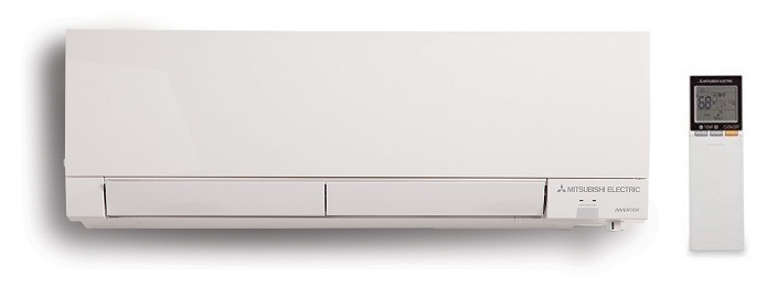
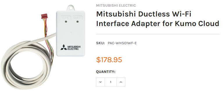
<p>I had 4 <a href="https://www.mitsubishicomfort.com/node/1103">Mitsubishi MSZ-FH09NA Heat Pumps</a> installed in my home.  They each came with a remote control but, being IR, I had to be in the room to use it.  This was an inconvenience when I needed change the temperature in my kids’ rooms while they were sleeping and not wake them.  Mitsubishi does offer an additional hardware adapter that allows connectivity over the internet for the heat pumps via an iOS or Android app.  I was shocked and disappointed to find out that the device would cost approximately $180 each.  For 4 units that would be around $1k total with tax!  Ouch!  Second, according to reviews, their app and service were not the best quality.  Third, the adapter attaches to the outside of the heat pump and looks ugly.</p>

<p><img src="/assets/images/mitsubishi_ductless_wifi_interface_adapter_for_kumo_cloud.jpg" alt="Mitsubishi Ductless Wifi Interface Adapter for Kumo Cloud Price" /></p>

<p>Eventually I came across a <a href="https://github.com/SwiCago/HeatPump">SwiCago’s Github project</a> that provides source code that implements the protocol used by the adapter to communicate with the heat pump using an Arduino.  This is based of the original work posted in <a href="https://nicegear.nz/blog/hacking-a-mitsubishi-heat-pump-air-conditioner/">this blog</a>. I don’t have much of a hardware background and I have never worked with Arduinos before, but it seemed rather simple.  I just had to order the same cable the Mitsubishi adapter uses and 4 Arduino chips.</p>

<p>You can check if your Mitsubishi Heat Pump model will work with this code by checking the <a href="https://github.com/SwiCago/HeatPump/wiki/Supported-models">supported models list</a> on SwiCago’s Github page.</p>

<h3 id="materials">Materials</h3>

<p>The Github project has part suggestions with links to online suppliers.</p>

<h4 id="cn105-cable">CN105 Cable</h4>

<p>The site I originally ordered my CN105 cables from is no longer in business.  The below should work.</p>

<p>https://m.aliexpress.com/item/1005002904897793.html (select 5P option)</p>

<h4 id="arduino">Arduino</h4>

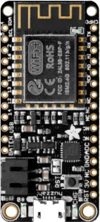
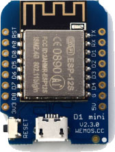
<p>I was originally planning on using the <a href="https://www.adafruit.com/product/2821">Adafruit Huzzah Feather ESP8266</a> since I saw from other implementers that they had luck with the device.  Also, the Huzzah could handle the 5V from the heat pump directly without requiring a 5V to 3.3V regulator.  I then saw posts where people said they were successfully using the Wemos D1 Mini.  The D1 Mini could also handle the 5V without a regulator but was also significantly cheaper.  The Huzzah costs close to $20 each.  You can get a <a href="https://www.amazon.com/Organizer-ESP8266-Internet-Development-Compatible/dp/B081PX9YFV/">pack of 5 Wemos D1 Mini (clones) for that much</a>.  The D1 was also much smaller and would fit better in tight spaces.  While the Huzzah is superior in other respects, the minimum requirements of what I needed for this project made the D1 Mini more desirable.</p>

<table>
  <thead>
    <tr>
      <th>Huzzah Feather ESP8266</th>
      <th>Wemos D1 Mini</th>
    </tr>
  </thead>
  <tbody>
    <tr>
      <td><img src="/assets/images/Huzzah_Feather_ESP8266.jpg" alt="Huzzah Feather ESP8266" /></td>
      <td><img src="/assets/images/Wemos_D1_Mini.jpg" alt="Wemos D1 Mini" /></td>
    </tr>
  </tbody>
</table>

<h4 id="micro-usb-to-usb-adapter">Micro-USB to USB Adapter</h4>

<p>You will also need a micro-usb to USB adapter to connect the Arduino to your computer to upload your code.  You likely already have one of these lying around.  Note that you can also update the code on your Arduino over Wi-fi, which will come in handy later after we install the chip inside the heat pump.</p>

<h4 id="other-things-you-will-need">Other Things You Will Need</h4>

<ul>
  <li>Soldering iron</li>
  <li>Solder</li>
</ul>

<h3 id="code">Code</h3>

<h4 id="setting-up-your-environment">Setting Up Your Environment</h4>

<p>Note: Instructions here are geared towards Windows but shouldn’t differ that much on other platforms.</p>

<p>Download and Install Arduino IDE</p>

<ul>
  <li>Navigate to https://www.arduino.cc/en/Main/Software</li>
  <li>Download the Arduino IDE for your platform and install it</li>
</ul>

<p>Configure Arduino IDE</p>

<ul>
  <li>Plug your Arduino into your machine using the micro-USB to USB cable</li>
  <li>Open Arduino IDE</li>
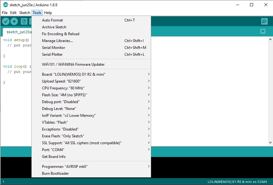
  <li>From the Tools menu you will need to select the board that matches your device.  In this case I am using the “LOLIN(WEMOS) D1 R2 &amp; mini” board.  After selecting this it will fill in some defaults.  Note: If you can’t find your board you can search for and download it from the Boards Manager.  In my case this was included in the esp8266 board package which supports a large number of boards.  To get this included in your list of boards to install, go to File &gt; Preferences, add a Boards Manager URL http://arduino.esp8266.com/stable/package_esp8266com_index.json.  Go back to the boards manager and search for esp8266 and install.</li>
</ul>

<p><img src="/assets/images/Arduino_IDE1.jpg" alt="Arduino IDE" /></p>

<ul>
  <li>Select the Port your device is on.  In my case, it is on COM4.  After this we should be able to upload code to the device.</li>
  <li>
    <p>Next, just to test that your setup and Arduino are working, lets upload some sample code that simply blinks the onboard LED.</p>

    <ul>
      <li>
        <p>From the file menu, select Examples &gt; ESP8266 &gt; Blink</p>
      </li>
      <li>
        <p>From the Sketch menu, select Upload</p>
      </li>
    </ul>
  </li>
</ul>

<p>If the upload completes successfully and the device is functioning correctly, you should see a blinking light on your Arduino</p>

<h4 id="working-with-the-heatpump-code">Working With the Heatpump Code</h4>

<p>Get the code</p>

<ul>
  <li>Navigate to https://github.com/SwiCago/HeatPump</li>
  <li>Click the “Clone or download” button</li>
  <li>Click “Download ZIP”</li>
  <li>Open the zip folder and copy the folder to your Arduino libraries folder (ex: c:\users&lt;username&gt;\documents\arduino\libraries)</li>
  <li>Move the examples folder to the arduino folder (ex: c:\users&lt;username&gt;\documents\arduino\examples)</li>
  <li>Restart Arduino IDE so it picks up the content you added</li>
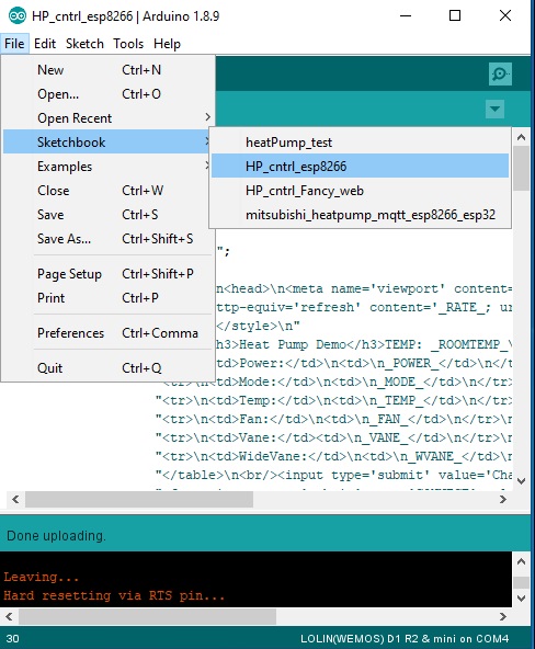
  <li>From the File menu, select Sketchbook &gt; HP_cntrl_esp8266</li>
</ul>

<p>This is a simple webserver that operates as a Wi-fi access point you can join to operate your heat pump.</p>

<p><img src="/assets/images/Arduino_IDE2.jpg" alt="Arduino IDE" /></p>

<ul>
  <li>
    <p>From the Sketch menu, select Verify/Compile
Note: you may get some dependency errors like the ones below for libraries that are not installed.<br />
    ArduinoJson.h: No such file or directory
    PubSubClient.h: No such file or directory</p>

    <p>If that is the case you can install them from the Tools menu by clicking “Manage Libraries…”.  From there, search for ArduinoJson and PubSubClient and install the packages.  Then try Verify/Compile again.  If successful, then upload the code to the device via the Sketch &gt; Upload menu item.</p>
  </li>
</ul>

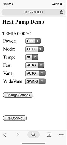
<p>The below is from the browser on my iPhone.  If the chip was connected to the heat pump it would be displaying the current settings.  This sample code provides basic functionality to allow you to access each of your heat pumps while you are at home and modify their settings.  Next, lets solder up our CN105 cable to the Arduino so we can plug it in to our heat pump.</p>

<p><img src="/assets/images/heat_pump_demo_screen.jpg" alt="Heat Pump Demo Screen" /></p>

<h3 id="soldering">Soldering</h3>

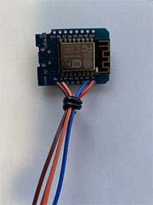
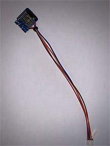
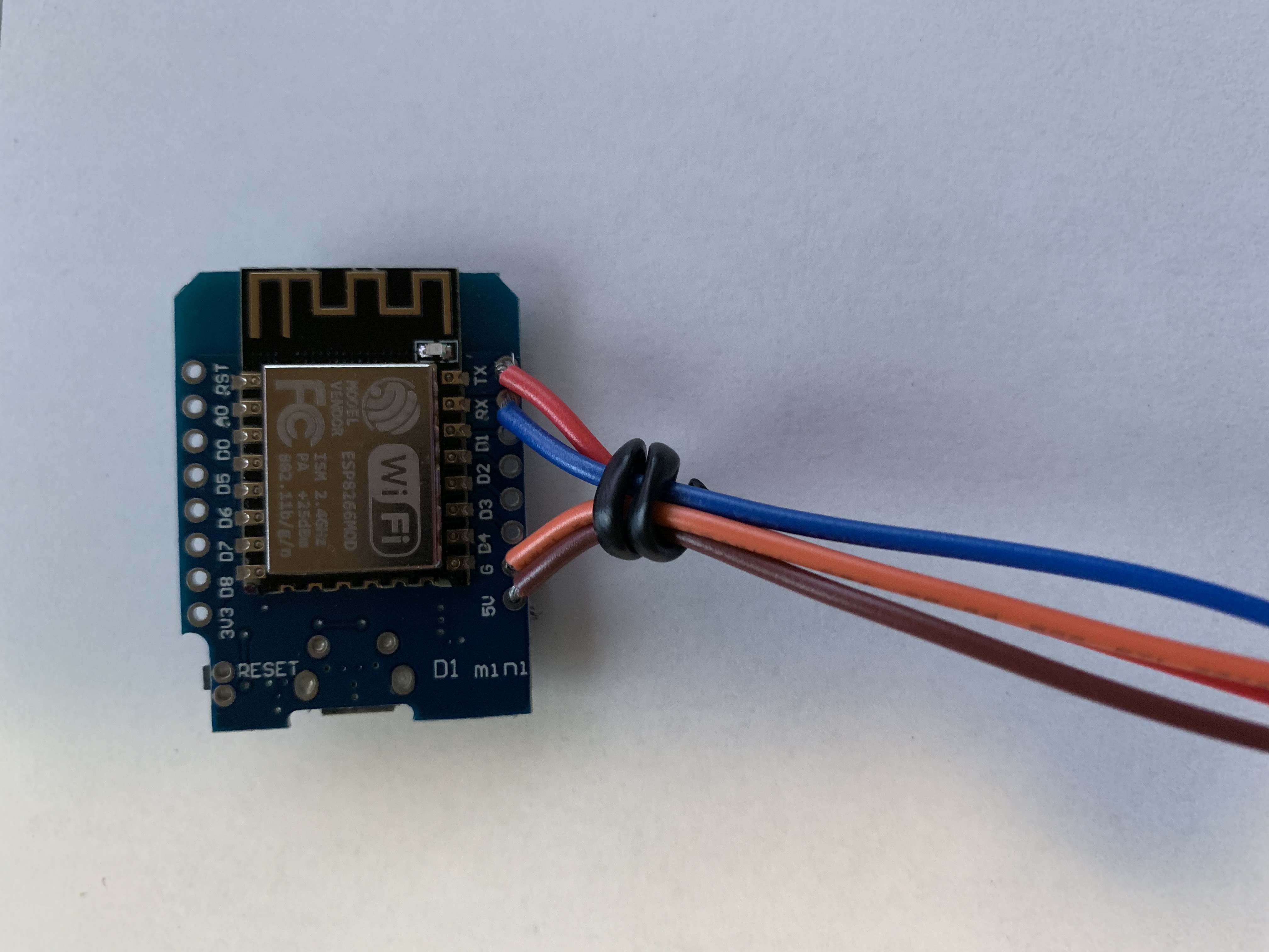
<p>I only needed 4 of the 5 wires on the premade cable.  Stripping and soldering the wires to the D1 was quick and easy.  I did all 4 chips in 20 minutes.</p>

<p>The 5V (brown) and ground (orange) pinouts are on the left, the RX (blue) and TX (red) on the right.  You can follow the cables below since your CN105 wire colors might be different</p>

<table>
  <tbody>
    <tr>
      <td><img src="/assets/images/Wemos_D1_Solder1.jpg" alt="Wemos D1 Soldered" /></td>
      <td><img src="/assets/images/Wemos_D1_Solder2.jpg" alt="Wemos D1 Soldered" /></td>
    </tr>
  </tbody>
</table>

<p><a href="/assets/images/wemosd1-hires.jpg">High resolution so you an see the pinouts</a></p>

<h3 id="installing">Installing</h3>

<p>I was a little hesitant to open up my heat pump at first.  They are certainly not cheap.  I was surprised how easy it was to take apart.</p>

<ul>
  <li>Turn off the heat pump.  You should really disconnect it from power if you can.</li>
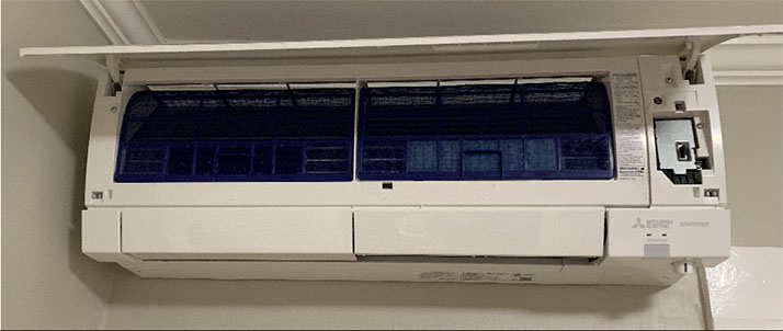
  <li>First, lift the main cover like the image below.  Then pull it away from the unit.  It should slide out of the hinges with a little wiggling.</li>
</ul>

<p><img src="/assets/images/heatpump_install1.jpg" alt="Install Step 2" /></p>

<ul>
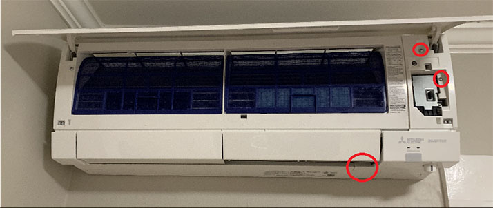
  <li>Remove screws at the below locations.  The area circled on the bottom is a little plastic piece that you can remove by hand which hides a screw.  With these removed you should be able to take off the right plastic shell.</li>
</ul>

<p><img src="/assets/images/heatpump_install2.jpg" alt="Install Step 3" /></p>

<ul>
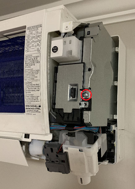
  <li>Remove the below screw and slide the right metal shielding away from the wall.</li>
</ul>

<p><img src="/assets/images/heatpump_install3.jpg" alt="Install Step 4" /></p>

<ul>
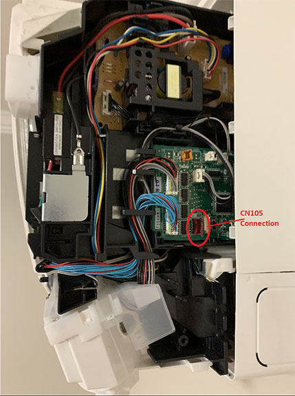
  <li>With the shielding removed, you should see the control board.  In the below image I point out the CN105 connection where you will connect the Arduino</li>
</ul>

<p><img src="/assets/images/heatpump_install4.jpg" alt="Install Step 5" /></p>

<ul>
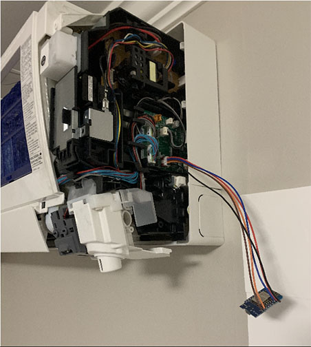
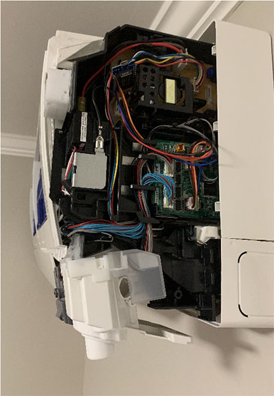
  <li>Plug in the device.  I tucked mine in the best I could where it wouldn’t be in the way when I slid the metal shielding back on over the control board.</li>
</ul>

<table>
  <tbody>
    <tr>
      <td><img src="/assets/images/heatpump_install5.jpg" alt="Install Step 6" /></td>
      <td><img src="/assets/images/heatpump_install6.jpg" alt="Install Step 6" /></td>
    </tr>
  </tbody>
</table>

<ul>
  <li>Turn the heat pump on.</li>
  <li>If you have the Wi-fi access point example installed on the chip you can try connecting to it to now to verify if it is reading the data on the heat pump.  Try modifying the settings as well.</li>
  <li>Put the heat pump case back together.</li>
</ul>

<h3 id="limitations">Limitations</h3>

<p>This is a simple setup to enable changing the settings on your heat pump from a browser.  A few things I didn’t like:</p>
<ul>
  <li>UI is not user friendly</li>
  <li>The Wi-fi Access Point seems flaky.  I kept getting dropped from my iPhone.  Not sure if it is just that device or not.  I didn’t use this solution for long so I didn’t troubleshoot it much.</li>
  <li>The example code didn’t enable OTA updates for the chip.  So I would have to physically take it out of the heat pump every time I wanted to update it.  Other examples do and it is pretty simple to add it.</li>
  <li>I need to connect to different access points to read/change settings on each of my heat pumps.</li>
  <li>I can’t connect to the heat pump over the internet - only when I am physically home.  I would like to get the house warm/cold before I get home.</li>
</ul>

<p>The good thing is that some of the other project examples leverage <a href="https://en.wikipedia.org/wiki/MQTT">MQTT (Message Queuing Telemetry Transport)</a> to allow communication across the internet.  Some home automation tools such as Hass.io leverage this.  I’ll cover those in my <a href="https://chrdavis.github.io/hacking-a-mitsubishi-heat-pump-Part-2/">next post</a>.</p>]]></content><author><name>Chris Davis</name></author><summary type="html"><![CDATA[I recently installed 4 heat pumps in my house to provide heat in the winter and AC in the summer time. While the weather year round in Seattle is fairly pleasant, there is about a month in the summer where life is miserable if you don’t have air conditioning - a rare luxury in residential homes in the Pacific Northwest. I had 4 Mitsubishi MSZ-FH09NA Heat Pumps installed in my home. They each came with a remote control but, being IR, I had to be in the room to use it. This was an inconvenience when I needed change the temperature in my kids’ rooms while they were sleeping and not wake them. Mitsubishi does offer an additional hardware adapter that allows connectivity over the internet for the heat pumps via an iOS or Android app. I was shocked and disappointed to find out that the device would cost approximately $180 each. For 4 units that would be around $1k total with tax! Ouch! Second, according to reviews, their app and service were not the best quality. Third, the adapter attaches to the outside of the heat pump and looks ugly. Eventually I came across a SwiCago’s Github project that provides source code that implements the protocol used by the adapter to communicate with the heat pump using an Arduino. This is based of the original work posted in this blog. I don’t have much of a hardware background and I have never worked with Arduinos before, but it seemed rather simple. I just had to order the same cable the Mitsubishi adapter uses and 4 Arduino chips. You can check if your Mitsubishi Heat Pump model will work with this code by checking the supported models list on SwiCago’s Github page. Materials The Github project has part suggestions with links to online suppliers. CN105 Cable The site I originally ordered my CN105 cables from is no longer in business. The below should work. https://m.aliexpress.com/item/1005002904897793.html (select 5P option) Arduino I was originally planning on using the Adafruit Huzzah Feather ESP8266 since I saw from other implementers that they had luck with the device. Also, the Huzzah could handle the 5V from the heat pump directly without requiring a 5V to 3.3V regulator. I then saw posts where people said they were successfully using the Wemos D1 Mini. The D1 Mini could also handle the 5V without a regulator but was also significantly cheaper. The Huzzah costs close to $20 each. You can get a pack of 5 Wemos D1 Mini (clones) for that much. The D1 was also much smaller and would fit better in tight spaces. While the Huzzah is superior in other respects, the minimum requirements of what I needed for this project made the D1 Mini more desirable. Huzzah Feather ESP8266 Wemos D1 Mini Micro-USB to USB Adapter You will also need a micro-usb to USB adapter to connect the Arduino to your computer to upload your code. You likely already have one of these lying around. Note that you can also update the code on your Arduino over Wi-fi, which will come in handy later after we install the chip inside the heat pump. Other Things You Will Need Soldering iron Solder Code Setting Up Your Environment Note: Instructions here are geared towards Windows but shouldn’t differ that much on other platforms. Download and Install Arduino IDE Navigate to https://www.arduino.cc/en/Main/Software Download the Arduino IDE for your platform and install it Configure Arduino IDE Plug your Arduino into your machine using the micro-USB to USB cable Open Arduino IDE From the Tools menu you will need to select the board that matches your device. In this case I am using the “LOLIN(WEMOS) D1 R2 &amp; mini” board. After selecting this it will fill in some defaults. Note: If you can’t find your board you can search for and download it from the Boards Manager. In my case this was included in the esp8266 board package which supports a large number of boards. To get this included in your list of boards to install, go to File &gt; Preferences, add a Boards Manager URL http://arduino.esp8266.com/stable/package_esp8266com_index.json. Go back to the boards manager and search for esp8266 and install. Select the Port your device is on. In my case, it is on COM4. After this we should be able to upload code to the device. Next, just to test that your setup and Arduino are working, lets upload some sample code that simply blinks the onboard LED. From the file menu, select Examples &gt; ESP8266 &gt; Blink From the Sketch menu, select Upload If the upload completes successfully and the device is functioning correctly, you should see a blinking light on your Arduino Working With the Heatpump Code Get the code Navigate to https://github.com/SwiCago/HeatPump Click the “Clone or download” button Click “Download ZIP” Open the zip folder and copy the folder to your Arduino libraries folder (ex: c:\users&lt;username&gt;\documents\arduino\libraries) Move the examples folder to the arduino folder (ex: c:\users&lt;username&gt;\documents\arduino\examples) Restart Arduino IDE so it picks up the content you added From the File menu, select Sketchbook &gt; HP_cntrl_esp8266 This is a simple webserver that operates as a Wi-fi access point you can join to operate your heat pump. From the Sketch menu, select Verify/Compile Note: you may get some dependency errors like the ones below for libraries that are not installed. ArduinoJson.h: No such file or directory PubSubClient.h: No such file or directory If that is the case you can install them from the Tools menu by clicking “Manage Libraries…”. From there, search for ArduinoJson and PubSubClient and install the packages. Then try Verify/Compile again. If successful, then upload the code to the device via the Sketch &gt; Upload menu item. The below is from the browser on my iPhone. If the chip was connected to the heat pump it would be displaying the current settings. This sample code provides basic functionality to allow you to access each of your heat pumps while you are at home and modify their settings. Next, lets solder up our CN105 cable to the Arduino so we can plug it in to our heat pump. Soldering I only needed 4 of the 5 wires on the premade cable. Stripping and soldering the wires to the D1 was quick and easy. I did all 4 chips in 20 minutes. The 5V (brown) and ground (orange) pinouts are on the left, the RX (blue) and TX (red) on the right. You can follow the cables below since your CN105 wire colors might be different High resolution so you an see the pinouts Installing I was a little hesitant to open up my heat pump at first. They are certainly not cheap. I was surprised how easy it was to take apart. Turn off the heat pump. You should really disconnect it from power if you can. First, lift the main cover like the image below. Then pull it away from the unit. It should slide out of the hinges with a little wiggling. Remove screws at the below locations. The area circled on the bottom is a little plastic piece that you can remove by hand which hides a screw. With these removed you should be able to take off the right plastic shell. Remove the below screw and slide the right metal shielding away from the wall. With the shielding removed, you should see the control board. In the below image I point out the CN105 connection where you will connect the Arduino Plug in the device. I tucked mine in the best I could where it wouldn’t be in the way when I slid the metal shielding back on over the control board. Turn the heat pump on. If you have the Wi-fi access point example installed on the chip you can try connecting to it to now to verify if it is reading the data on the heat pump. Try modifying the settings as well. Put the heat pump case back together. Limitations This is a simple setup to enable changing the settings on your heat pump from a browser. A few things I didn’t like: UI is not user friendly The Wi-fi Access Point seems flaky. I kept getting dropped from my iPhone. Not sure if it is just that device or not. I didn’t use this solution for long so I didn’t troubleshoot it much. The example code didn’t enable OTA updates for the chip. So I would have to physically take it out of the heat pump every time I wanted to update it. Other examples do and it is pretty simple to add it. I need to connect to different access points to read/change settings on each of my heat pumps. I can’t connect to the heat pump over the internet - only when I am physically home. I would like to get the house warm/cold before I get home. The good thing is that some of the other project examples leverage MQTT (Message Queuing Telemetry Transport) to allow communication across the internet. Some home automation tools such as Hass.io leverage this. I’ll cover those in my next post.]]></summary></entry></feed>